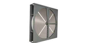
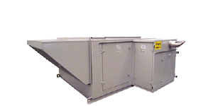
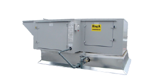
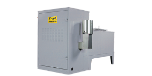
HRP Series
Industrial Air to Air Thermal Recovery Units with QDT Heat Pipe
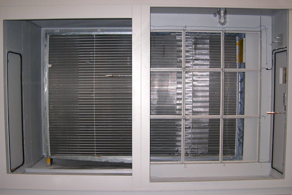
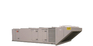
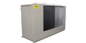
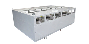
Engineered Air’s HRP Series is an energy recovery package specifically designed to reduce the high cost of conditioning ventilation air by recovering a significant portion of the thermal energy from the exhaust air. This is accomplished with Engineered Air’s QDT Heat Pipe which has a nominal 60% recovery factor.
Engineered Air also uses QDT technology in a HRP Wrap Around Heat Pipe for passive dehumidification and reheat applications.
Features
- Energy savings
- Choice of blower types
- Gas, electric, hot water or glycol heating
- Chilled water or DX cooling coil
- Indoor and outdoor
- Filter options
- Automated optimization of heat pipe sizing
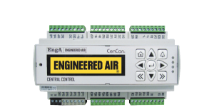
- Dedicated Engineered Air NextGen digital controllers
*Due to continuous product development, specifications, dimensions and capacities are subject to change without notice.
What is a Heat Pipe?
Engineered Air’s HRP Series is an energy recovery package specifically designed to reduce the high costs of conditioning ventilation air by recovering a significant portion of the thermal energy from the exhaust air. This is accomplished with Engineered Air’s QDT Heat Pipe which has a nominal 60 percent recovery factor.
How the Heat Pipe Works?
The HRP Series heat pipe is a counterflow air-to-air heat exchanger. While it has the outward appearance of an ordinary plate fin chilled water or steam coil, it differs in one major aspect. Rather than each tube being connected to another by a return bend or header, each individual tube is a heat pipe. Operating independently, the heat pipes act as superconductors of heat.
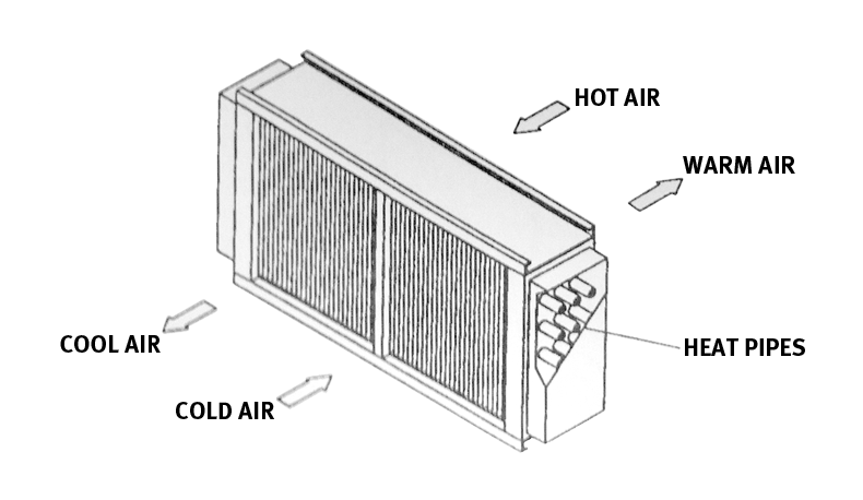
Figure 1: Typical Heat Pipe
The heat pipe is a tube which has been fabricated with an integral capillary wick structure, evacuated, filled with refrigerant and permanently sealed. Thermal energy applied to either end of the pipe causes the refrigerant liquid at that end to evaporate. The refrigerant vapour then travels to the other end of the pipe where the removal of thermal energy causes the vapour to condense into liquid again, releasing the latent heat of condensation. The condensed liquid then flows back to the evaporator section to be reused, thereby completing the cycle. The heat pipe thus operates in a closed loop evaporation / condensation cycle whih is continuous as long as there is a temperature difference to drive the process. The capillary wick action is provided by the circumferentially grooved inner wall (shown below). This wicking action insures the entire inner surface is wet with refrigerant, therefore maximizing thermal capacity.
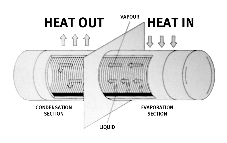
Figure 2: Theory of Operation
Although the heat pipes span the width of the unit, a sealed partition separates the two airstreams, thus preventing cross contamination between them.
Incoming supply air is passed through one side of the heat pipe and exhaust air is passed through the other side in a counterflow direction. Energy from the hotter air flow is transferred by heat pipes to the other side of the unit where it is captured by the colder air flow. The outside air is therefore either heated or cooled depending on the relative temperatures of the air streams.
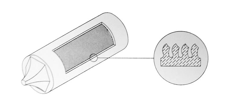
Figure 2: Theory of Operation
The capacity of a heat pipe to transfer thermal energy can be regulated by changing the orientation of the pipe relative to horizontal. Lowering the evaporator section (hot air side) of the heat pipe below horizontal increases the heat transfer capacity as gravity assists in returning the condensate flow to the hot air side of the heat pipe. Conversely, raising the evaporator end above horizontal decreases or stops heat transfer capability since the condensate has to flow against gravity.

