C-TRAC Cooling Sequencer
It is the highest level of the TRAC Family. Other Engineered Air TRAC controllers can be slaved to the C-TRAC. The slaved heating controller receives a 0-10VDC control signal from the C-TRAC.
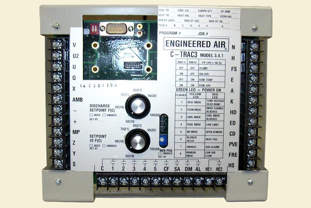
C-TRAC
Cooling Sequencer
The TRAC family of product specific controls have been designed:
- To provide precise control, white also incorporating operating and safety limits
- To eliminate electro-mechanical devices, (switches, relays, etc) by means of logic based programming.
- To provide rugged, dependable controllers than can withstand the rigors of a rooftop installation. The ability to operate at -40°F ambient and in the presence of electronic noise are essential
Technical Data | |
|---|---|
Power Supply: 24 VAC - 10VA Contact Rating: 70VA @ 24VAC, 360VA @ 120VAC Inrush Rating: 1800VA |
|
| Digital Inputs (DI): 3 | Digital Outputs (DO): 5 |
|
|
| Analog Inputs (AI): 4 | Analog Outputs (AO): 2 |
|
|
| Ambient Operating Temperature Limits | Temperature Sensors |
Maximum: 105°F ( 40°C ) Minimum: -40°F ( -40°C ) |
1000 ohm Thin Platinum Positive Temperature Coefficient Devices (PTC) |
| Economizer Minimum Position | Dead Band |
0 - 100% |
Fully adjustable 5°F to 12°F |
| Timing Functions | Control Algorithms |
|
|
View Brochure PDF Request Access to our Complete Catalog
Due to continuous product development, specifications, dimensions and capacities are subject to change without notice.
G-TRAC Industrial Gas Heater Controller
Together the DG high turndown burner and the G-TRAC controller provide optimum air heater performance.
The G-TRAC is a stand-alone controller for the Engineered Air series DG Industrial Furnance. Alternatively it can be slaved from the C-TRAC Cooling Sequencer for integrated control of a packaged air conditioner, such as the Engineered Air FW-DG, or a split system using a DG heat section and a CU condensing unit.
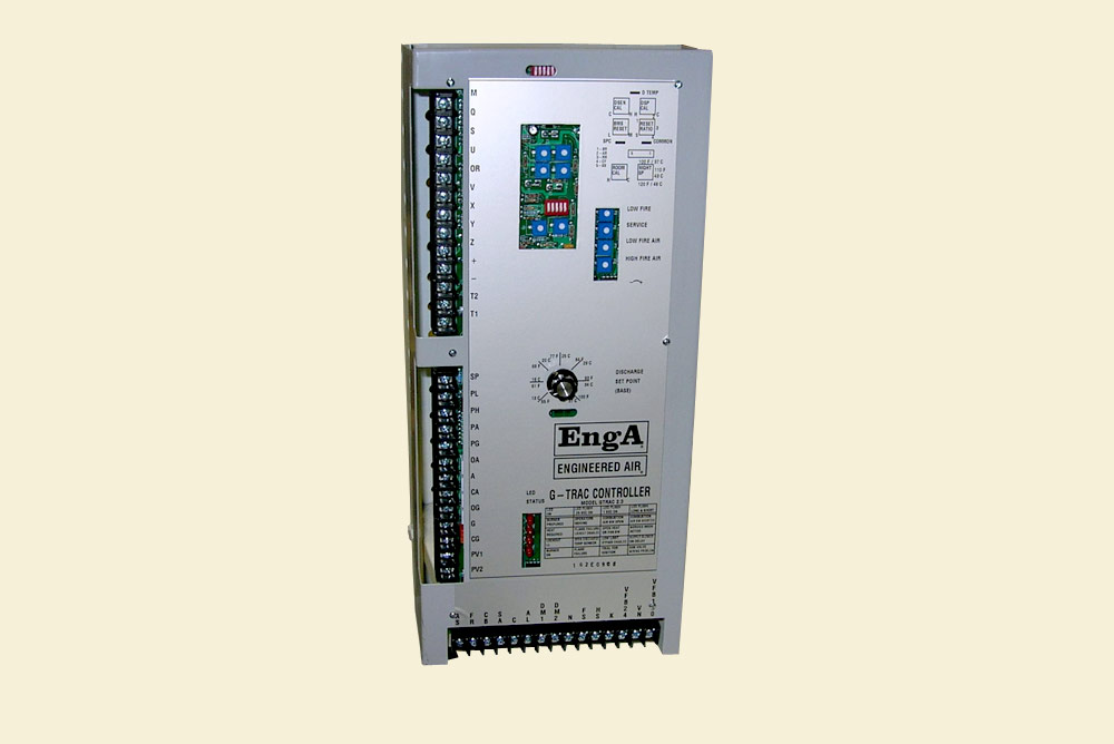
G-TRAC
Industrial Gas Heater Controller
Technical Data | |
|---|---|
Power Supply: 24 VAC Contact Rating: 70VA @ 24VAC, 360VA @ 120VAC Inrush Rating: 1800VA |
|
| Digital Inputs (DI): 4 | Digital Outputs (DO): 8 |
|
|
| Analog Inputs (AI): 6 | Status Indication: |
|
4 LED's on face of panel provide status information including the following:
|
| Ambient Operating Temperature Limits | Temperature Sensors |
Maximum: 105°F ( 40°C ) Minimum: -40°F ( -40°C ) |
1000 ohm Thin Film Platinum Positive Temperature Coefficient Device (PTC) |
View Brochure PDF Request Access to our Complete Catalog
Due to continuous product development, specifications, dimensions and capacities are subject to change without notice.
DJM Controller
The DJM controller is a programmed logic device that provides proportional-integral control when used with any one of the DJ series burners. The basic function of the DJM is to control discharge air temperature. The discharge air setpoint can be set either at a fixed value, or can be reset from a number of options.
The DJM in its various forms can operate as either a stand-alone controller, or it can be interfaced with our C-TRAC mechanical cooling controller.
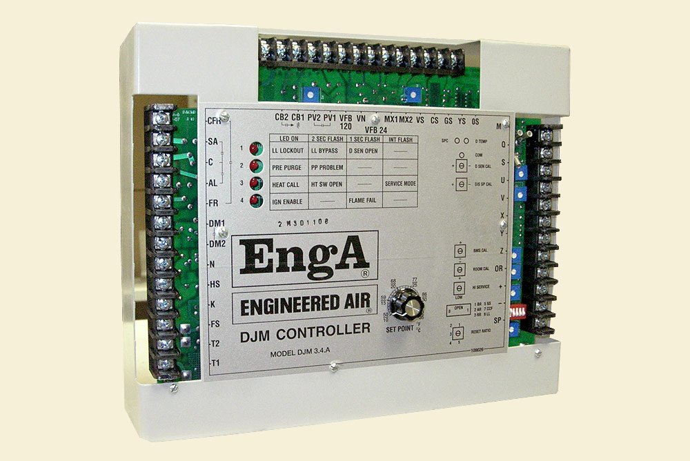
DJM Series
Controller
Technical Data | |
|---|---|
Power Supply: 24 VAC Contact Rating: 70VA @ 24VAC, 360VA @ 120VAC Current Draw: 1.2 amps |
|
| Digital Inputs (DI): 4 | Digital Outputs (DO): 5 |
|
|
| Analog Inputs (AI): 6 | Analog Outputs (AO): 2 |
|
|
| Status Indication | Ambient Operating Temperature Limits |
4 LED's on face of panel.
|
Maximum: 105°F ( 40°C ) Minimum: -40°F ( -40°C ) |
| Temperature Sensors | |
| 1000 ohm thin film platinum Positive Temperature Coefficient Device (PTC) | |
View Brochure PDF Request Access to our Complete Catalog
Due to continuous product development, specifications, dimensions and capacities are subject to change without notice.
H-TRAC Heat Sequencer
The electric heat coil controlled by an H-TRAC controller is specifically designed with stages sized for operation with the binary control logic. Stage one is smallest, stage two is double stage one, and stages three, four and five are each four times the output of stage one. In this manner by activating various combinations of the physical stages, fifteen "equivalent" control stages are created (7 or 11 equivalent stages can also be provided.)
The H-TRAC can be used in a variety of control applications. Avaliable options are:
- Discharge air control with 135 Ω proportional controller
- Discharge air control with Maxitrol electronic sensor and setpoint adjustment
- Room control with modulating high and low limits
- 0-10VDC or 4-20MA reset of discharge air setpoint
- Direct control from a higher level controller (i.e. H-TRAC becomes a slaved controller)
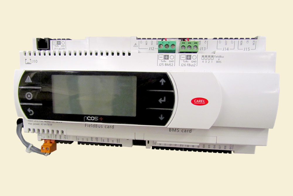
H-TRAC
Heat Sequencer
Technical Data | |
|---|---|
Power Supply: 24 VAC Current Draw: 6VA Contact Rating: 70VA @ 24VAC, 360VA @ 120VAC Inrush Rating: 1800VA |
|
| Digital Inputs (DI): 0 | Digital Outputs (DO): 5 |
| None. |
|
| Analog Inputs (AI): 4 | Analog Outputs (AO): 0 |
|
None. |
| Status Indication | Ambient Operating Temperature Limits |
One LED behind panel. |
Maximum: 105°F ( 40°C ) Minimum: -40°F ( -40°C ) |
View Brochure PDF Request Access to our Complete Catalog
Due to continuous product development, specifications, dimensions and capacities are subject to change without notice.
Q-TRAC QDT Heat Pipe Controller
Controlling the rate of heat transfer via tilt angle of the heat pipe has three objectives.
- Temperature control: supply air temperature leaving the heat pipe.
- Frost Prevention: maximizing heat transfer while preventing the formation of frost on the exhaust leaving side of the coil.
- Heating-Cooling changeover: by reversing the tilt angle, the direction of heat transfer is also reversed to allow summer operation.
The Q-TRAC control is a stand alone solid state device that provides proportional-integral control for all three functions when mounted on a QDT heat pipe with tilt mechanism.
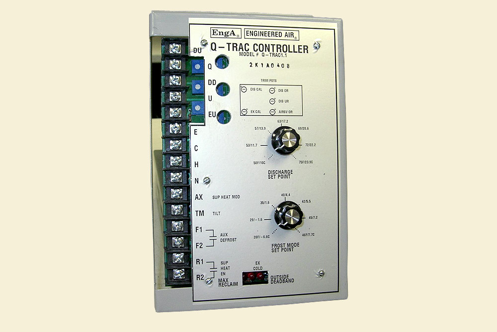
Q-TRAC
QDT Heat Pipe Controller
Technical Data | |
|---|---|
Power Supply: 24 VAC Contact Rating: 70VA @ 24VAC, 360VA @ 120VAC |
|
| Digital Inputs (DI): 2 | Digital Outputs (DO): 2 |
|
|
| Analog Inputs (AI): 2 | Analog Outputs (AO): 2 |
|
|
| Status Indication | Ambient Operating Temperature Limits |
3 LED's on face of panel.
|
Maximum: 105°F ( 40°C ) Minimum: -40°F ( -40°C ) |
| Temperature Sensors | |
| 1000 ohm thin film platinum Positive Temperature Coefficient Device (PTC) | |
View Brochure PDF Request Access to our Complete Catalog
Due to continuous product development, specifications, dimensions and capacities are subject to change without notice.
W-TRAC Heat Wheel Controller
The W-TRAC controller is designed to provide variable speed control for an Engineered Air heat wheel. By controlling the rotational speed of the head wheel, and in turn controlling the rate of heat transfer, three functions can be accomplished.
- Control of supply air temperature leaving the head wheel.
- Prevention of frost formation on the exhaust side of the wheel while keeping heat transfer at the maximum allowable level.
- Heating-Cooling changeover. In heating mode heat is carried from the warm exhaust to the cold outside air. In cooling mode heat transfers from the warm outside air to the cooler exhaust air. The wheel simply rotates in either case and as such there is no difference in operation between heating and cooling. By stopping the wheel completely a free cooling mode can be provided. This is desirable if cooling is required and outside air is colder than the exhaust air.
The W-TRAC controller is a stand alone solid state device that provides proportional / integral control for all three of the above functions when mounted with an Engineered Air wheel.
When combined with a DC drive motor the W-TRAC can provide exceptional high turndown speed control. DC drive motors offer the advantage of high torque ability at very low speeds. The W-TRAC can also provide a 0-10 vdc control signal to a variable frequency drive if conditions require the use of an AC drive motor.
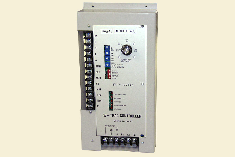
W-TRAC
Heat Wheel Controller
Technical Data | |
|---|---|
Power Supply: 24 VAC Contact Rating: 48VA @ 4VAC, 240VA @ 120VAC |
|
| Digital Inputs (DI): 0 | Digital Outputs (DO): 2 |
| None. |
|
| Analog Inputs (AI): 5 | Analog Outputs (AO): 2 |
|
|
| Status Indication | Ambient Operating Temperature Limits |
5 LED's on face of panel.
|
Maximum: 105°F ( 40°C ) Minimum: -40°F ( -40°C ) |
| Temperature Sensors | |
| 1000 ohm thin film platinum Positive Temperature Coefficient Device (PTC) | |
View Brochure PDF Request Access to our Complete Catalog
Due to continuous product development, specifications, dimensions and capacities are subject to change without notice.
M-TRAC 1, 2, 3 Controller
The M-TRAC controller has eliminated many mechanical parts such as air proving switch, damper end switch, timers and relays. The M-TRAC provides interlock between the exhaust fan and the make up air unit. This allows the M-TRAC to prove the operation of both the exhaust fan and supply fan. Reverse interlock is also available. This feature is designed for use in buildings which should not go into a negative pressure condition during start up mode.
The Engineered Air M-TRAC controller is designed to be user friendly. The controller is equipped with five diagnostic LED lights. System status can be determined by the LED color and its flashing patterns. This features allows easier troubleshooting.
The M-TRAC in its various forms can operate as either a stand-alone controller, or it can be interfaced to a higher level controller such as a C-TRAC or programmable controller. When used as a stand-alone device the controller provides most of the control requirements of a make up air unit. Standard abilities include: discharge temperature control, supply blower control, burner management, inlet damper control, auto bypass low limit, and air flow monitoring.
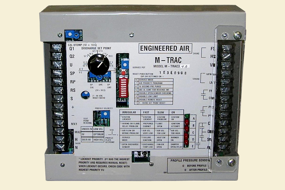
M-TRAC
1.3 Controller
Technical Data | |
|---|---|
Power Supply: 24 VAC Contact Rating: 72VA @ 24VAC, 360VA @ 120VAC Current Draw: 1.2 amps |
|
| Digital Inputs (DI): 5 | Digital Outputs (DO): 5 |
|
|
| Analog Inputs (AI): 5 | Analog Outputs (AO): 1 |
|
|
| Status Indication | Ambient Operating Temperature Limits |
5 LED's on face of panel. Based on flashing rate these lights indicate:
|
Maximum: 120°F ( 49°C ) Minimum: -40°F ( -40°C ) |
| Temperature Sensors | |
| 1000 ohm thin film platinum Positive Temperature Coefficient Device (PTC) | |
View Brochure PDF Request Access to our Complete Catalog
Due to continuous product development, specifications, dimensions and capacities are subject to change without notice.
S-TRAC Humidifier Controller
The Engineered Air S-TRAC controller is a programmed logic controller. It has eliminated many mechanical parts such as timers, relays and water level controller. The S-TRAC provides water level, burner, humidity and system status control. It also has a built in drain cycle timer. The S-TRAC controlled SH humidifier will initiate a drain cycle depending on the hardness of the water and the firing rates of the burner. A mixing valve is also incorporated in the S-TRAC to eliminate high drain temperature.
The S-TRAC can be used in a variety of control applications.
- Room humidity control c/w S-TRAC built-in setpoint
- Room humidity control c/w BMS 0-10VDC setpoint
- Return air humidity control c/w S-TRAC built in setpoint
- Return air humidity control c/w BMS 01-10VDC setpoint
- BMS 4-8VDC direct control
- Ambient reset (to prevent unwanted condensation forming on windows and walls)
- Duct high humidity limit
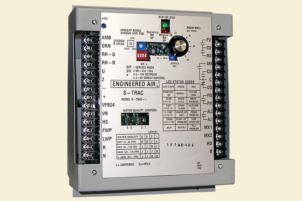
S-TRAC
Humidifier Controller
Technical Data | |
|---|---|
Power Supply: 24 VAC Contact Rating: 70VA @ 24VAC, 360VA @ 120VAC Current Draw: 6VA Inrush Current: 1800 VA |
|
| Digital Inputs (DI): 3 | Digital Outputs (DO): 4 |
|
|
| Analog Inputs (AI): 5 | Analog Outputs (AO): 1 |
|
|
| Status Indication | Ambient Operating Temperature Limits |
2 LED's on face of panel. Based on flashing rate these lights indicate:
|
Maximum: 105°F ( 40°C ) Minimum: -40°F ( -40°C ) |
| Temperature Sensors | |
| 1000 ohm thin film platinum Positive Temperature Coefficient Device (PTC) | |
View Brochure PDF Request Access to our Complete Catalog
Due to continuous product development, specifications, dimensions and capacities are subject to change without notice.
X-TRAC Controller
The X-TRAC through the use of digital electronics, has eliminated many of the traditional control components resulting in fewer parts, simplified wiring diagrams and reduced wiring. The X-TRAC replaces the Maxitrol Series 21 amplifier & auto bypass low limit.
The X-TRAC uses a control scheme incorporating Proportional and Integral control (PI) to maintain discharge temperature at set point.
The X-TRAC was designed to be easily applied to the following control applications:
- Discharge control with internal or remote setpoint
- Two level room control. When room thermostat closes, discharge temperature is reset upward to a second discharge set point
- Discharge control c/w external 4-20MA or 0-10VDC reset from BMS. Reset amount ranges from 5°F to 50°F
X-TRAC has built in non-recycling auto bypass low limit. It also has a self-check feature that ensures that the discharge sensor is operating within its tolerances. Two built-in status lights for heat call & lock out are provided.

X-TRAC
Controller
Technical Data | |
|---|---|
Power Supply: 24 VAC Contact Rating: 70VA @ 24VAC, 360VA @ 120VAC 0.8 amps |
|
| Digital Inputs (DI): 4 | Digital Outputs (DO): 2 |
|
|
| Analog Inputs (AI): 4 | Analog Outputs (AO): 1 |
|
|
| Status Indication | Ambient Operating Temperature Limits |
2 LED's on face of panel. Based on flashing rate these lights indicate:
|
Maximum: 105°F ( 40°C ) Minimum: -40°F ( -40°C ) |
| Temperature Sensors | |
| 1000 ohm thin film platinum Positive Temperature Coefficient Device (PTC) | |
View Brochure PDF Request Access to our Complete Catalog
Due to continuous product development, specifications, dimensions and capacities are subject to change without notice.
